Overview
Juniors in the electrical engineering department at Princeton may elect to complete a semester long independent work project under the supervision of a faculty advisor. During the fall semester of 2016, I had the opportunity to work with Professor Dan Marlow and Senior Research Physicist Norm Jarosik from the physics department on a project to conduct ranging measurements of the moon. This project included the design and implementation of RF systems to interface USRP software defined radios with the TLM-18 dish and the development of Python software to perform collection and post-processing of data.
Acknowledgments
This project was supported by funding from the Princeton University Department of Electrical Engineering and the Princeton University School of Engineering and Applied Science (SEAS). In addition, many thanks to Professor David Wentzlaff (EE) and Professor Joe Taylor (Physics) for their valuable input and advice over the course of this project.
RF System Design
Receive Hardware
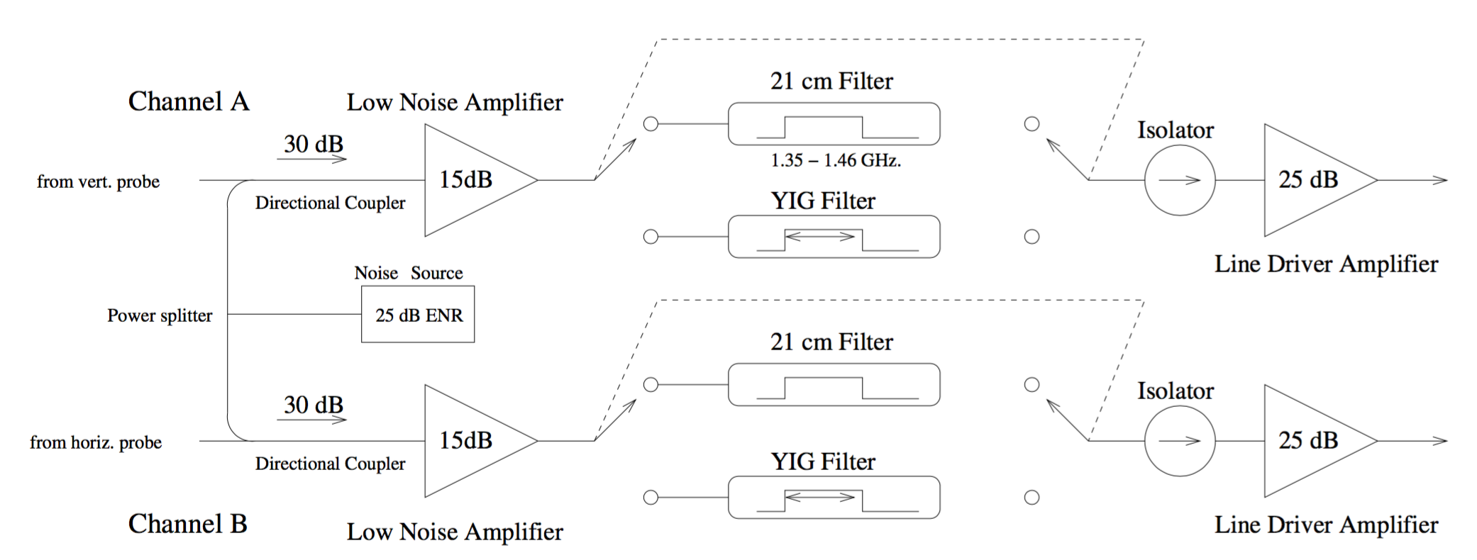 Receive path block diagram
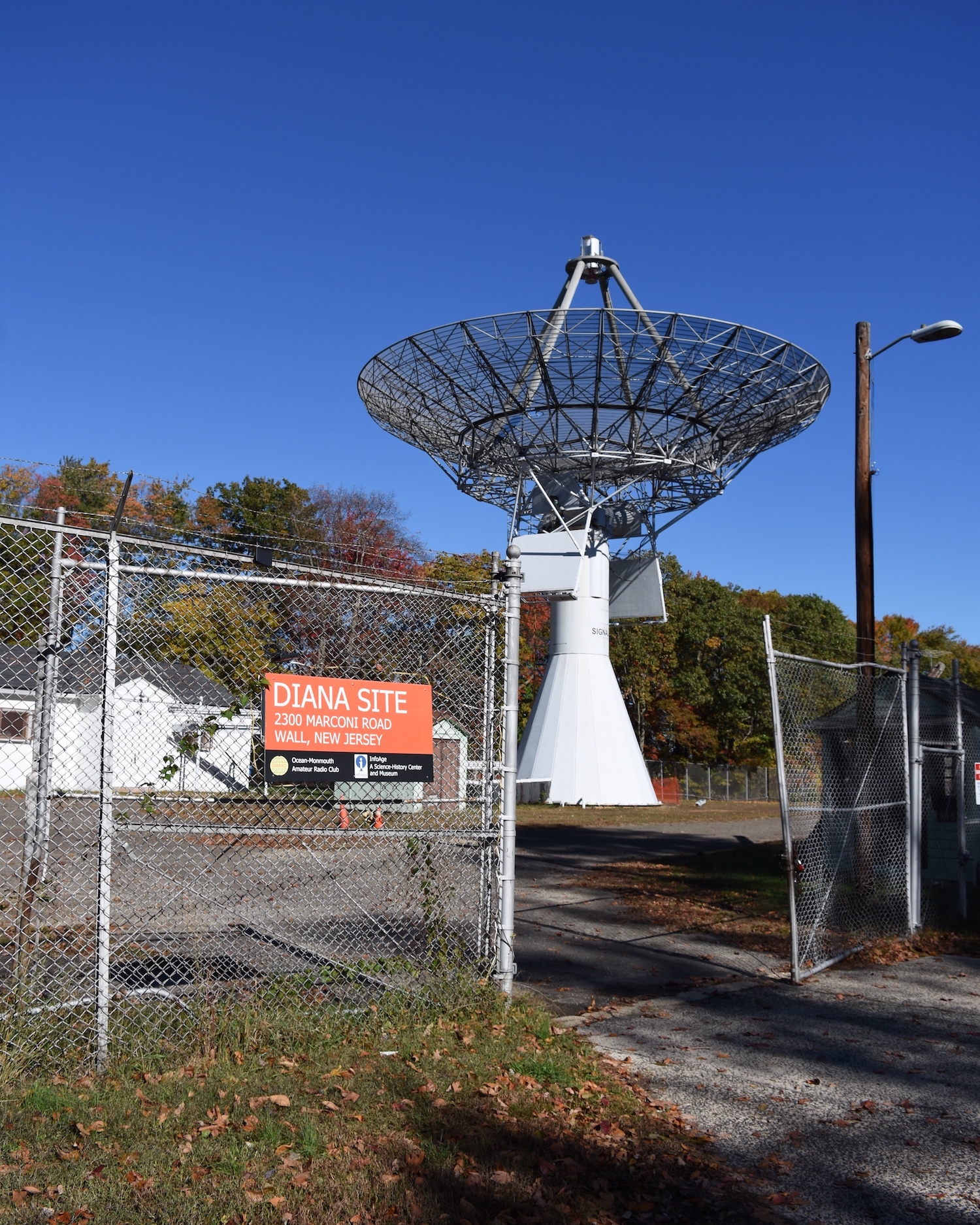
The TLM-18 antenna is an 18m-diameter microwave dish located at the former Project Diana site about 40 miles from campus. Prior to this independent work project, various faculty members refurbished the dish and installed hardware for making radio astronomy measurements at a 21cm wavelength. This existing hardware includes low-noise-amplifiers (LNA’s) and microwave filters for enabling the reception of weak signals.
Transmit Hardware
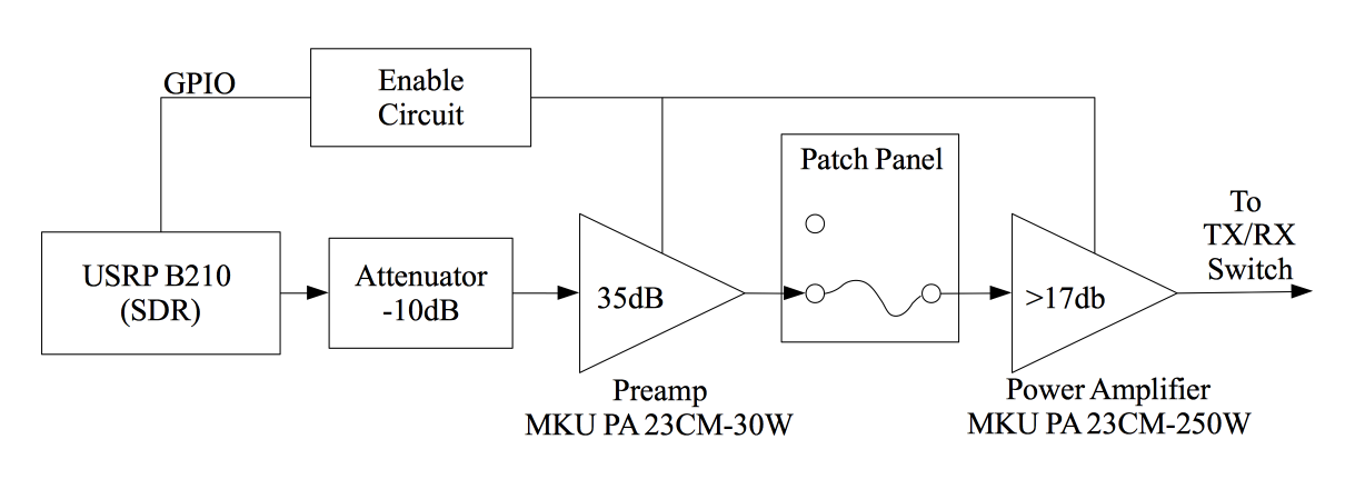 Transmit path block diagram
While the receive path of the TLM-18 antenna was already in place, additional hardware was necessary to enable transmit functionality. In particular, a series of microwave-frequency amplifiers were needed to increase the transmit power of the USRP radios. The USRP B210s being used have a transmit power output of about 10mW, while about 10W is required to drive the existing transmit power amplifier.
 Amplifier panel under test
We ultimately selected a Kuhne MKU PA 23CM - 30W Power Amplifier. Attenuators were added between the USRP and Kuhne amplifier to ensure the amplifier output would never exceed the 10W input limit. A RF patch panel allowed the output of the amplifier to be connected in place of the amateur radio tranceiver already installed at the site.
Control Circuitry
To disable the amplifier during receive, a small circuit was built to allow the USRP's built-in GPIO pins to toggle the 12V enable line on the Kuhne amplifier. This interface circuit output was also connected to the existing sequencer circuit, which controls the transmit-receive switches and high-power amplifiers.
Transmit Waveform
A literature review identified many different options for the transmitted waveform. Since the echo from the moon would be shifted a large amount both in time and in frequency, any coding scheme used needed to have good frequency-domain resolution as well as time-domain resolution.
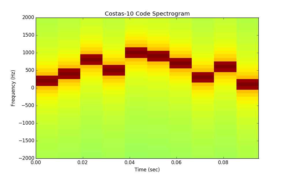 Costas-10 code spectrogram
It was ultimately decided to use a class of codes known as Costas codes. These codes consist of a sequence of values, sent via FSK, with excellent correlation properties both in time and in frequency. The exact waveform used was a Costas-10 code using 10 distinct frequencies sent in a 0.1 sec interval.
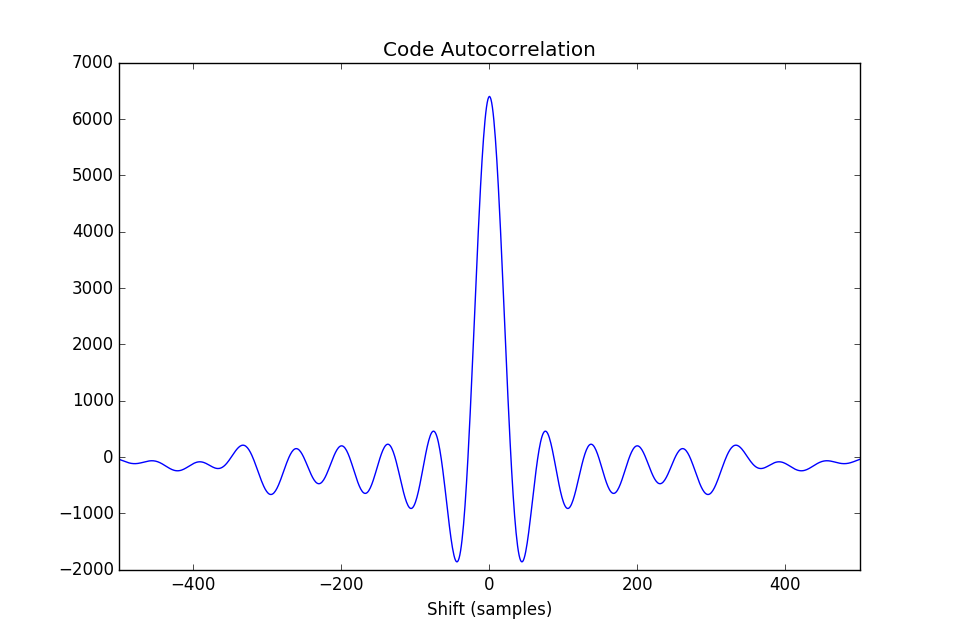 Costas-10 code time-domain autocorrelation
The complex waveform was generated and analyzed using the SciPy Python package.
Radio Control
Interfacing with the USRP B210 software defined radios was accomplished through the GNURadio open-source toolkit. A Python script coordinated the transmit-receive switching, waveform transmission, and data collection.
Post-processing
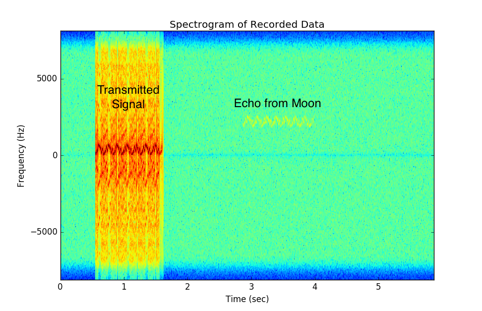 Example spectrogram of received data
The echo from the moon could be clearly seen in the received data. Matched filtering was performed using SciPy to identify the transmitted waveform.
Sample Rate Recovery
During analysis it became evident that there was a major discrepancy in the sample timing. It appeared almost as if the samples were being recorded with half the specified sample rate. Further testing revealed that running the script with the GUI interface enabled was causing heavy load on the computer, leading to buffer overuns and dropped samples.
Given the limited time available, which precluded another recording session, we attempted to recover basic timing information from the recorded based on the delay between the start of recording and the start of transmission. By making the simplifying assumption that the packet loss happened at a consistent rate, missing samples could be modeled as a deviation in the sample rate.
Timing Data
| Trial Number | Recovered "Actual" Sample Rate (Hz) | Round trip time (sec) | Earth-Moon Distance (km) |
|---|---|---|---|
| 1 | 656719 | 2.307 | 345839 |
| 2 | 656643 | 2.308 | 345921 |
| 3 | 662131 | 2.307 | 345814 |
| 4 | 642116 | 2.388 | 357998 |
| 5 | 643052 | 2.364 | 354283 |
| 6 | 650329 | 2.345 | 351518 |
| 7 | 649577 | 2.343 | 351194 |
| 8 | 660327 | 2.307 | 345768 |
| 9 | 641099 | 2.380 | 356727 |
| 10 | 661004 | 2.253 | 337681 |
| Average | 652300 | 2.330 | 349274 |
| 2 sigma | 16346 | 0.083 | 12422 |
Conclusion
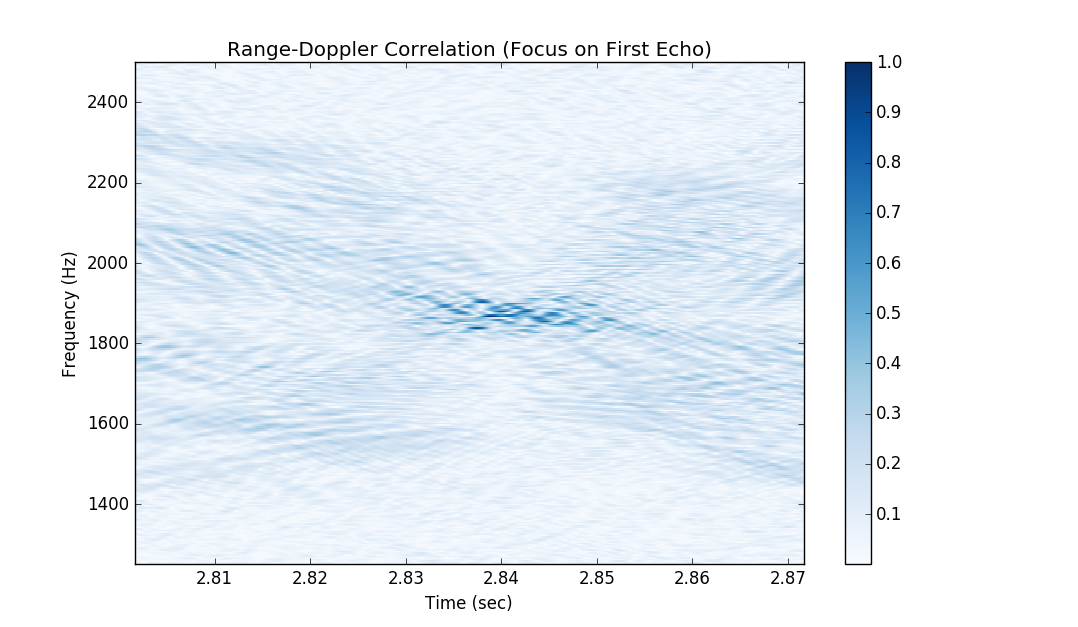 Example range-doppler correlation output
The TLM-18 dish was successfully upgraded with the hardware systems necessary to perform ranging experiments at 23-cm wavelength. Averaging across ten trials, the round trip time for a signal to traverse the Earth-Moon-Earth path was measured to be 2.33±0.08 sec, corresponding to a Earth-Moon distance of 350000±10000 km.
Calculations based on accepted lunar orbit data place the expected distance to the moon between 364043 and 364006 km during the observation period. As noted above, the likely source of this error is dropped samples due to excessive load on the computer running the USRP control scripts. Nevertheless, this result is remarkably close given the first-order approximation used to recover the sample rate.
Overall, this project demonstrates the viability of performing Earth-based active radar astronomy with relatively low-cost experimental setups. It is hoped that the methods used and problems encountered will be instructive for others seeking to begin their own foray into the field of radar astronomy.