Business Card
In preparation for the fall recruiting season of senior year, I decided to make a PCB business card. While I had seen other examples of PCB cards before, most of them either had no circuitry or focused on microcontroller-based circuits. For my card, I wanted to take a middle route which took advantage of the aesthetic possibilities of PCB design while demonstrating some simple electrical functionallity.
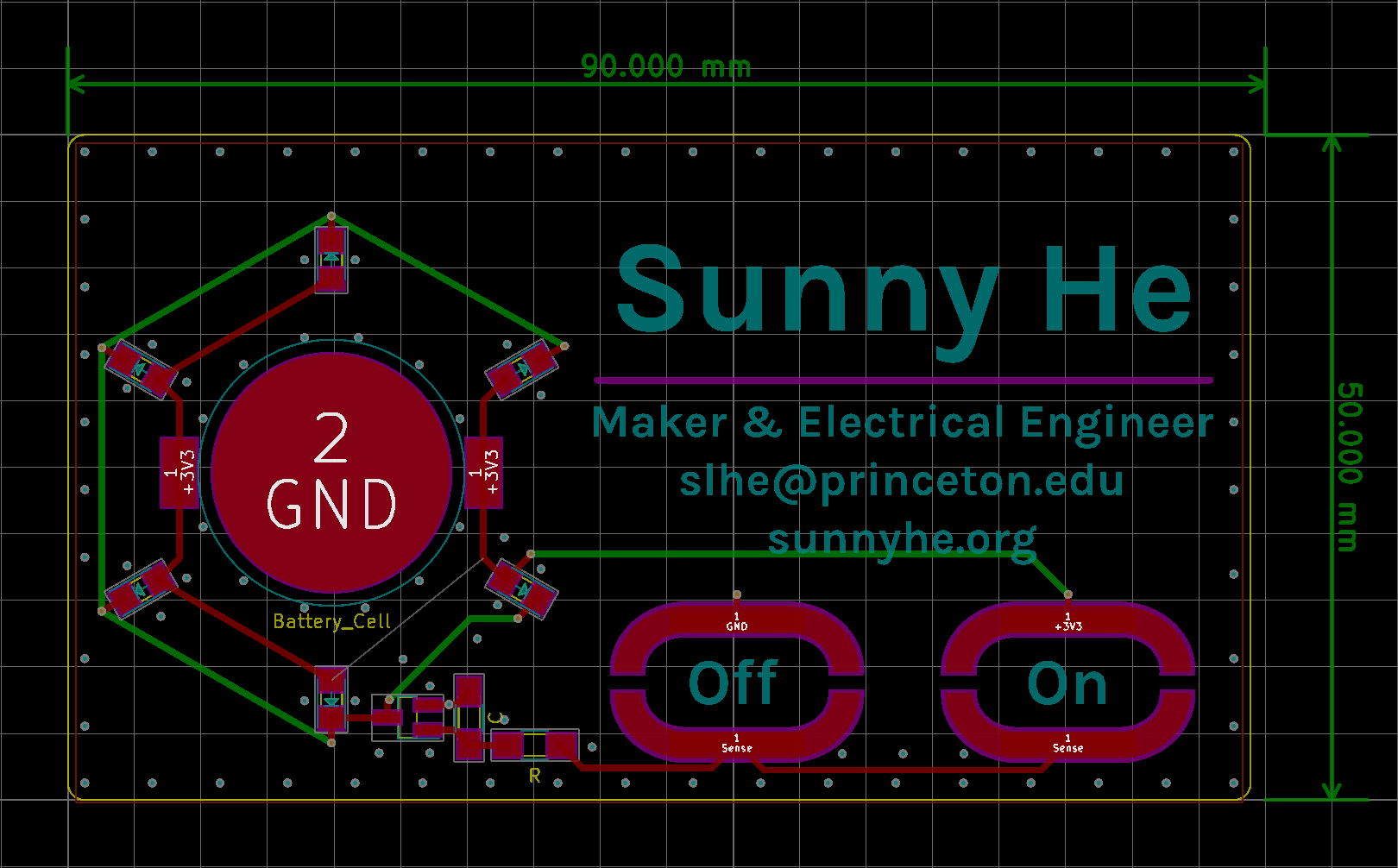
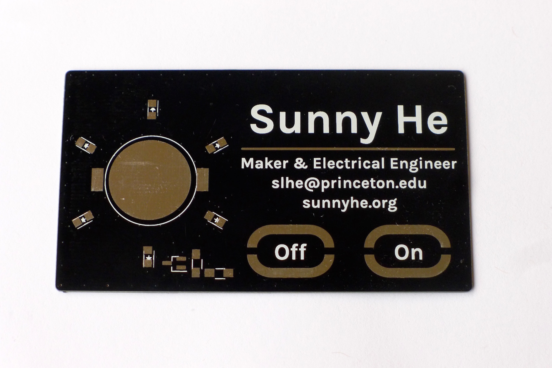
The final design has two touch pads that turn the ring of yellow LED's on and off. The circuitry is powered by a standard 2032 coin cell. The front of the card has my name and basic contact info, and the back silkscreen shows a copy of the board schematic.
Design files are posted in this Github repo.
Circuit Description
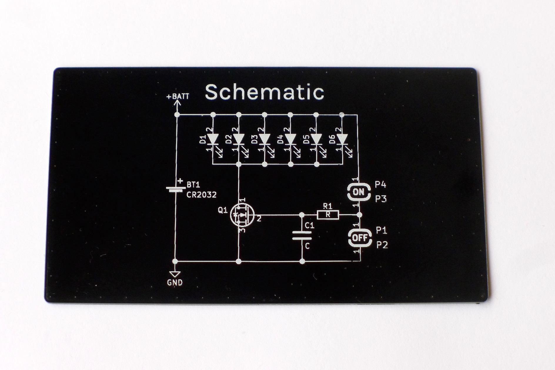
While the circuit may seem quite simple, it takes advantage of a number of non-obvious properties to make touch control possible. The N-MOSFET acts as a standard low-side switch, turning the yellow LED's on and off. The CR2032 coin cell supplies 2.8-3.0V, and its own internal resistance provides current limiting for the LED's.
The touch pads rely on skin conductivity to charge up the gate capacitance of the MOSFET. While for most purposes skin may seem like an insulator, people are suprisingly conductive. Some quick work with a multimeter showed most people's fingers seemed to be range between 10 and 20 MOhm. The MOSFET on the board also isn't an ideal component. There is a small but still significant capacitance between the gate and source of the MOSFET. In the case of the FDV301N MOSFETS used on this board, the input capacitance is specified to be about 9.5pF.
When a person bridges one pair of touch pads with their finger, this formes an RC circuit with a time constant of about 0.1-0.2 milliseconds. Pressing on the "ON" button charges the gate capacitance, turning the MOSFET on, while pressing the "OFF" button discharges the gate capacitance, turning the MOSFET off. A series resistor is added on the input line to help suppress stray induced currents, which would cause the LED's to flicker or turn on without being touched. The value is not critical, as long as it is relatively small compared to skin resistance. I also added pads for an extra capacitor to be added in parallel to the MOSFET's gate capacitance to tune the time constant, but ultimately this proved unnecessary.
Design Process
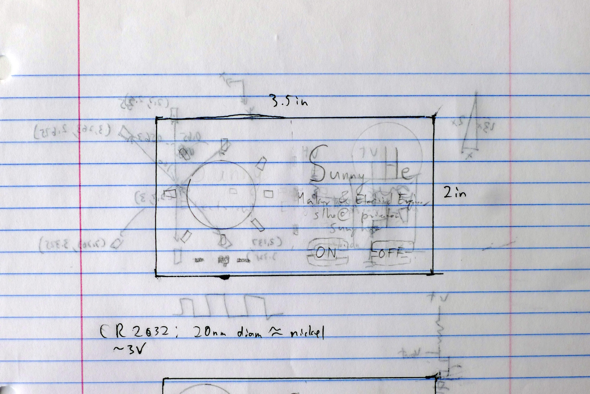
I performed the inital brainstorming and rough design on paper, mocking up different options with pencil in a ink 3.5x2" rectangle. I had the idea for the MOSFET-based touch circuit from earlier work, but there were some special design contraints to work with for this board.
- Size: The board must be within the normal business card size of 3.5x2", and be low-profile enough to carry around
- Components: While surface-mount components were mandatory to reduce the thickness of the card, I didn't have access to a reflow oven. To ease hand-soldering, all components had to be at least 1206.
- Simplicity: Use as few components as possible and avoid IC's.
- Clarity: My name and contact information had to be prominently featured. This is a business card after all.
- Aesthetics: It had to look good.
I eventually settled on a star formation of LED's arranged around the battery, taking advantage of the dominating circular form to evoke a classic star or "sun" shape.
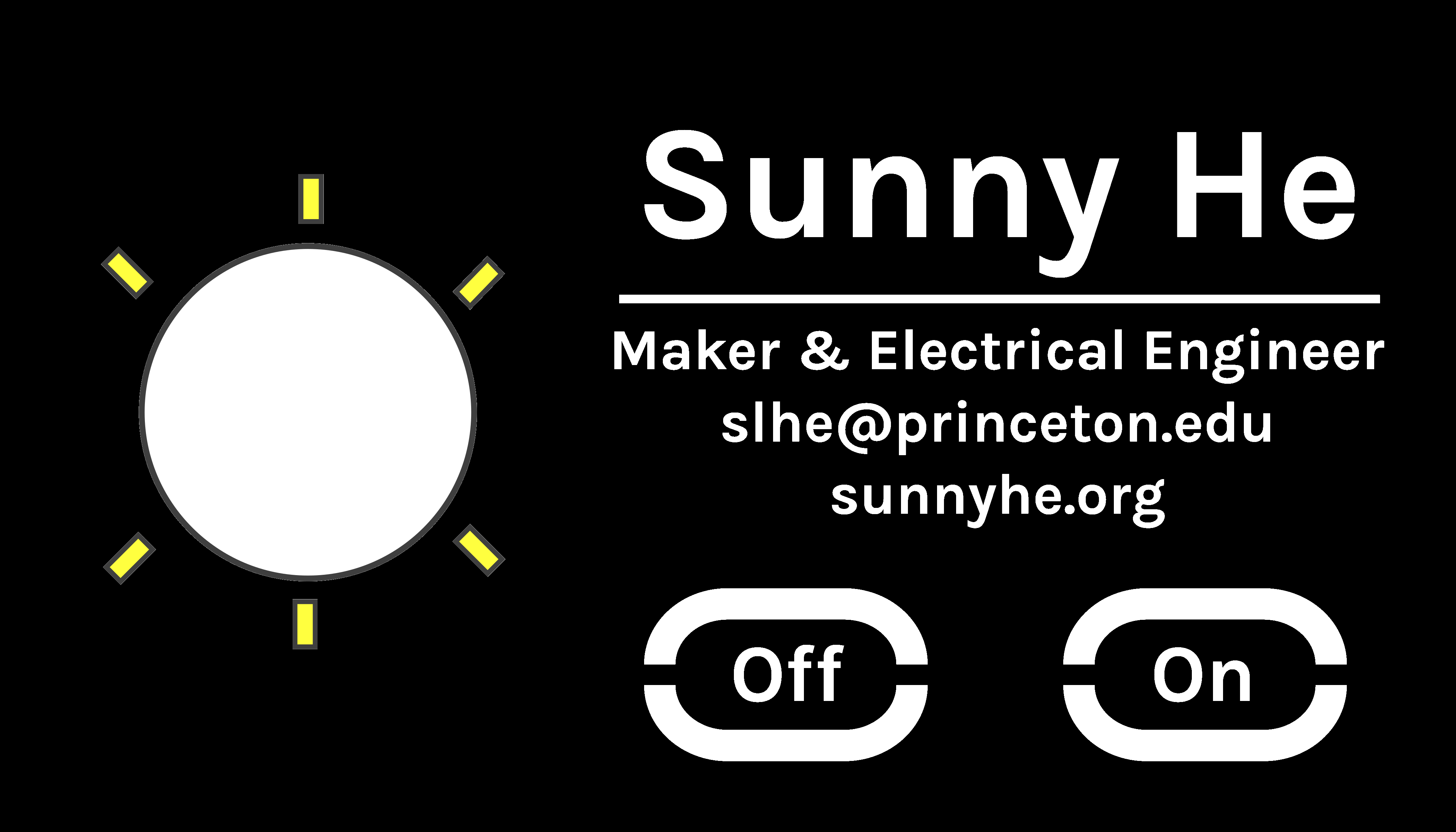
Next the design was finalized in Inkscape as an SVG vector file. I used the Google Fonts tool to find the Karla font used for all the lettering.
PCB Layout
Manufacture and Assembly
Bill of Materials
| Part | Manufacturer | Part Number | Quantity (per board) | Price (per board) | Source |
|---|---|---|---|---|---|
| Yellow LEDs | Lite-On | LTST-C150KSKT | 6 | 6 x $0.288 @ 36 Units | [Mouser](https://www.mouser.com/ProductDetail/?qs=BwFLjhzUaKkzXUKRSgwLjg%3D%3D) |
| N-Channel MOSFET | ON/Fairchild | FDV301N | 1 | $0.156 @ 15 Units | [Mouser](https://www.mouser.com/ProductDetail/ON-Semiconductor-Fairchild/FDV301N/) |
| 1KOhm Resistor | Yaego | RC1206FR-071KL | 1 | $0.024 @ 10 Units | [Mouser](https://www.mouser.com/ProductDetail/Yageo/RC1206FR-071KL/) |
| Battery Holder | Linx Technologies | BAT-HLD-001 | 1 | $0.280 @ 5 Units | [Mouser](https://www.mouser.com/productdetail/linx-technologies/bat-hld-001) |
| CR2032 Coin Cell | Panasonic | CR2032 | 1 | $0.330 @ 5 Units | [Mouser](https://www.mouser.com/ProductDetail/658-CR2032) |
| PCB | Elecrow | 1 | $2.59 @ 10 Units | [Elecrow](https://www.elecrow.com/10pcs-2-layer-pcb.html) | |
| Total: | $5.11 |